8051 LED TOGGLE PROGRAM CODE
You might have seen a "Hello World!" program code example while learning some programming language. While it is useful for getting familiar with the basics of that language, it also gives you a head start in that environment. If you ever want to learn some new programming language, you might want to Google out a "Hello world!' program code to get started. The code I am about to discuss serves the same purpose for the 8051 microcontroller because it is the most simplest task to perform. Play close attention if you want everything to work properly.
LED TOGGLE
LED (Light Emitting Diodes) are simple lights that you can turn ON/OFF. They glow when they are ON and they don't when they are not. They look somewhat familiar to the picture below
 |
| Standard RED LEDs |
The bigger leg represents the POSITIVE terminal while the shorter one is definitely NEGATIVE. So you take care of the legs when you use them (high voltage goes to POSITIVE while NEGATIVE is connected to GROUND of the power supply). In our diagrams, we are used to representing it with the symbol as shown so don't get confused. The left terminal is POSITIVE while the right end is NEGATIVE terminal.
 |
| LED Symbol |
INTERFACING LED TO 8051
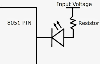
There are two genuine methods of interfacing (in simple words, connecting) LED to your 8051. Both will work just fine but have opposite programming techniques.
 |
| LED INTERFACE 1 |
 |
| LED INTERFACE 2 |
The resistor is important in interface 2 to limit the flowing current and avoid damaging the LED and/or MCU but I wouldn't care much about the resistor in interface 1 as 8051 MCU won't/can't damage the LED but let's not go into the safety problems. If you ask me, I would go for interface 1 without using any resistor at all! because it has worked for me every time.
I will explain the program code in detail but let me tell you beforehand, as a conceptual hint, the difference between these two interfaces.
- Interface 1 will glow LED ONLY if the PIN value is HIGH as current flows towards ground.
- Interface 2 will glow LED ONLY if the PIN value is LOW as current flows towards PIN due to its lower potential.
PROGRAM CODE
Let me go straight into the code now. I will explain both Assembly and C Language code so let's get started. You can download the program code in ZIP form by following the link in the download section at the end of this post. I am sure you know how to create HEX file using KEIL and then simulate the code using PROTEUS and when you're done verifying your code, you can easily program the 8051 MCU.
For practical testing, you will need a test circuit for the 8051 MCU which is the most fundamental requirement of the project and you can't help but implement it for successful output. Honestly, it's very simple once you get used to it, I promise.
It will be tricky to explain each portion of the code. You need to learn ASSEMBLY Language to understand it all properly. The flow of the program is such that it togglesPIN1.0 of PORT1. In other words,
- Move 00000001 to PORT1 (each port is 8bit wide)
- Wait for some time
- Move PORT1 value to accumulator where we can complement it using CPLand thus it becomes 11111110 (PIN1.0 is being toggled)
- Move this new value back to PORT1
- Wait for some time and repeat the process.
So the value of PIN1.0 keeps toggling (ON/OFF) after some delay. The delay is implemented by using three nested loops. The loops will run 10 x 200 x 200 times and I don't know the exact amount of time it takes because I am not interested in it at the moment. For now, let's just say that the delay is long enough for the human eye to witness the LED blinking.
The same code in C language will look somewhat like this
 |
| C LANGUAGE CODE |
As you can see, it becomes relatively easier to write in C language. Just use normal C operators to manipulate data and values. Now the most important thing in this code is that it is good practise to give the MCU an infinite task to do (by using infinite while loop) so that it will never get out of the loop, stop and just sit there looking at your face. It must constantly perform some operation.
The delay function used in this code is also a general one and it roughly provides the required delay in milliseconds as defined by the input parameter. So we are talking of one second when we say delay(1000). You can use this function for now but don't ever use it when timing is crucial and you need more accuracy.
Here is the simulation design for PROTEUS that I used. As I said, I wouldn't care much about the resistor. Neither in the simulation nor in practical scenario.
 |
| PROTEUS SIMULATION DESIGN |
I have also included the design file in the download package. I hope that this post has given you an idea of how things are done in real. It gets easier with practise. Any suggestion/feedback is highly appreciated as I might have missed something. Remember that there is always an easier way around in programming so I encourage you to learn, understand and then venture on your own adventure. Goodluck for the implementation.

No comments:
Post a Comment